
Recently, a large industrial firm presented several hydraulic test system manufacturers with a challenge: develop a system to simulate a field installation for factory set-up and testing. Naturally everyone jumped at the chance for a line-up. Then the required system’s capabilities were outlined as follows:
“We are looking for a systems solution provider who can build a system to test several sizes of hydraulic power unit (HPU) assemblies. We would also like to simulate various hydraulic cylinders which will not be utilized at the factory, but only operated in the field. Then, based upon historical operational parameters of an installed system, determine presets to limit field adjustments and system tuning. Of course you’ll need to calculate and display recommended system settings and automatically preset components for factory test technicians. Also, monitor and record the system settings, perform simulated position and load sweeps, provide factory shipment setpoint data, and automatically generate a documentation package for the field installation crew. Lastly, apply this to over 35 hydraulic power unit designs, 9 cylinder diameters, 4 standard stroke lengths, and up to 64 system combinations. Can you help?”
Their request was simply met with a blank stare by most. Genuen's response was “Absolutely,” as it seemed to be a natural fit. Over the past several years, Genuen has become known for our electronic Hardware-in-the-Loop (HIL) systems. Customers have used these HILs across a variety of product technologies, including steering systems, variable valve timing, ride stability control, airbag control modules, and aerospace flight surfaces. So, we simply viewed the challenge above as another kind of HIL: “Hydraulics-in-the-Loop”.
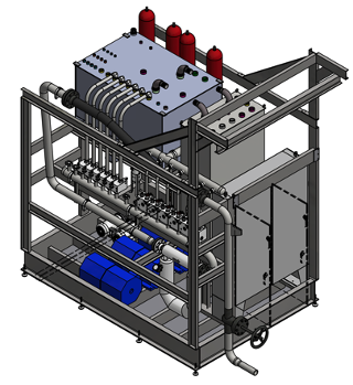
Figure 1.Main Test Frame (shown without guarding)
Staging of the Test
The test starts with an HPU being staged at the test stand. The technician connects the unit, both hydraulically and electrically, and then scans the unit’s “job order” via a bar code scanner. This identifies the application, the HPU’s size, the cylinder parameters, and the overall operational requirements. The system is now ready to start the testing process.
Let the Testing Begin
The test starts by deriving the data to simulate the final installed configuration of the HPU and cylinder combination. First, the system pulls the type of cylinder(s), bore diameters, rods, and stroke length(s). Then, from those inputs, the required operational flows, system loads and required pressures, cylinder speeds, number of positions, and overall expected system timing are compiled into the job requirements.
Testing of the Hydraulic Power Unit Assembly
The testing of the HPU consists of first pulling the operational data of the 35 different HPUs from a database. Then the system identifies the HPU in use, its volume, the pump and motor being utilized, and operational pressures and flows. Once the unit’s data has been uploaded, the system steps the operator through a process of filling the unit, checking interlocks, starting the motor, setting the relief valve pressure, and checking pump flow. The system then records associated data and stores it within the job’s test parameter database. After fully testing, the HPU is drained for shipment.
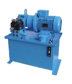
Figure 2. A example of a generic hydraulic power unit assembly
Simulation of the Field-Installed Cylinders
The simulation of the cylinders is achieved by imparting actual flows, system pressures, backpressures (induced loads), and usage volumes for the field-installed assembly. In this way, the control valving could be preset to mimic actual operational characteristics. This methodology limited the amount of field adjustments required and dramatically reduced installation times. The 9 cylinder diameters, multiple stroke lengths, and varying styles resulted in a total of 64 possible system combinations.
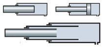
Figure 3. Nine (9) Cylinder Diameters, Multiple Styles, and Four (4) Stroke Lengths are utilized
Simulation of a Field-Installed System
With the omission of the actual cylinders during factory testing, several operator screens were developed to aid the technician in evaluating system operation and sequences. Control valving can be automatically or manually set over multiple cycles. Easy-to-read, live graphs provide system flow, pressure, and cylinder position vs. time. Additional display parameters allow the technician to monitor all aspects of the system on dual 24” monitors.
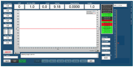
Figure 4. One of the four Main Test Screens available on two 24” system monitors
Documentation Package
A final documentation package is generated and ships with each system. Valve set points are included in addition to system and test parameters. To enable field service crews to restore the system to factory defaults, the physical position of the valve’s handle adjustments are also recorded. This provides some peace-of-mind against end users accidentally “tweaking” the system outside of operational parameters.
Success Outcome
The customer is currently utilizing two of these systems and is looking forward to installing a third to meet ever-increasing production requirements. This simulation solution greatly reduced their field installation and start-up times, eliminated the need to have actual cylinders present for system testing, and resulted in a quick return on investment!
A detailed Case Study of this application can be found below.

Contact Genuen for Your System Evaluation
Are you looking for help with simulation, Hardware-In-Loop (HIL), designing electromechanical test cells, or supporting an existing system? We offer data acquisition and control systems which are custom designed to your requirements.
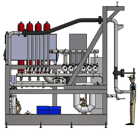
Figure 5.The system’s side view gives a better idea of the actual physical size of the test stand (guarding removed)
Systems can be engineered to be upgraded in “add-on” modules or phases. This way, the investment for a total system upgrade can be spread out over several budget cycles.
For more information on hydraulic simulations systems, contact Genuen for an application evaluation today.