Industry: Construction
Application: Fluid Power Testing
 The Challenge
Design and build a turn-key system to test entire hydraulic systems without using any physical field-installed actuators, and do so in such a way that the system requires little-to-no field adjustments once installed. In addition, the system must confirm the proper operation of the hydraulic power unit (HPU) and associated valving assembly, automatically pre-tune the system’s valving, and generate the necessary documentation for “plug-and-play” installation.
 Background
The stand required a tremendous amount of testing flexibility to meet all of the customer’s requirements, including:
- Each cylinder must have multiple, programmable stop positions
- The cylinder(s) will have multiple, varying speeds
- The extension and retraction loads will vary, not only from HPU-to-cylinder, but must also be variable at each stop position along the total usable stroke
- Automatically vary the test pressure range of approximately 400 psi
- Automatically vary the test fluid flows throughout an approximate range of 550 gpm
- Provide an allowance for a 25% flow expansion
- Allow for up to 35 hydraulic power unit configurations including:
- Varying pressures unit-to-unit
- Varying flows unit-to-unit
- Varying control valve configurations including both analog and digital control
- Allow for up to 64 HPU and cylinder combinations including:
- Varying cylinder and rod diameters
- Varying rod types
- Single and multiple cylinders being tested in combination
- Varying cylinder travel distances up to 300 inches
- Automatically varying the simulated loads on each cylinder
- Preconfigured automated test sequences, operator selectable combinations, and full manual control options
- Definable system alarms for load control out of tolerance, over-current, high-temperature, low-pressure, etc. for all system combinations
- A custom test interface to allow for users and bar-coded data via Bluetooth
- Custom data logging and reporting
 The Solution
Genuen (formerly WTI) engineered, manufactured, and installed two fully integrated Hydraulic Simulation and Test Systems to meet our customer’s requirements. This included the complete operational testing of over 35 HPUs, setup and adjustment of all control valving, simulation of multiple combinations and types of field-installed hydraulic cylinders, simulation of each system’s operation in the field, and documentation package automation. The possible component-selection matrix resulted in over 64 system configurations to be supported.
The system’s capability included the following operational parameters:
- Test an HPU assembly for functionality.
- Simulate various hydraulic cylinders, which will not be utilized at the factory, but were only to be installed/operated in the field.
- Determine system preset adjustments, based upon historical final operational parameters of a field-installed system, to limit field adjustments and system tuning.
- Calculate and display recommend system settings, including automatically pre-setting components where possible for the factory test technician.
- Monitor and record system settings, perform simulated position/load sweeps, provide factory setpoint data, and provide documentation for the field-installation crew.
- Then to apply this to 35 HPU designs, 9 cylinder diameters, 4 standard stroke lengths, and up to 64 system combinations!

Figure 1. The Test Stand Assembly measures 100” wide x 166” deep x 177” high.
Genuen developed a custom solution to fully test HPUs and corresponding unit-mounted control valving, and to perform cylinder simulations in one test. To provide the operator with a physical sense of cylinder movement, the control screen portrays simulated cylinder graphics that extend and retract with varying loads.
The solution eliminated the need to connect cylinders, which could surpass 50 feet when extended, and mitigated the previous requirement to change out mechanical loads. Instead, the hydraulic system was designed to generate or accept inlet and outlet volumes, operational pressures, load pressures, cylinder stop points, cylinder feedback positions, and control valve interaction as if a cylinder existed.
Via automatic selection by model number or manual selection of an HPU, test profiles preload cylinder diameter and length, number of cylinders, number of extension and retraction stops and positions, load applied to the cylinder, cylinder speeds, etc.
The test operation was designed to function with as little operator setup as possible. An operator hooks up HPU hydraulic lines to the test stand, connects power to the HPU, interconnects the control wiring harness from the HPU to the test stand, scans in the bar-coded test specification, and presses the start button.
The cycle starts as the system fills the HPU to its proper level, starts the unit, and checks pump outlet flow, maximum system pressures, and operational pressures. It then makes recommendations so that the technician can dial in pressure(s) while monitoring and viewing the display for a system-recommended corrective action.
Once the HPU is set-up, the system energizes and de-energizes control valving to control the simulated cylinder, as it automatically makes valve adjustments (to be detailed in another document); records the valve’s flow(s), pressures(s), and adjustments; and calculates recommendations for operator interventions. It then identifies when the operator’s adjustments were correct and complete. When all settings are completed, the system runs one final cylinder sweep and records setpoints and historical data. Lastly, it compiles a job summary to be sent with the system to the job site.
In addition to a cylinder sweep test, the system is capable of running a cylinder leak-down test, where it detects leakage within the control valving, an overspeed detection test, and determination of valving operation on a falling load, for specific applications.
The system then automatically resets, drains the unit, and readies itself for the next system test.
Building the Muscle of the Test Rig
Genuen developed a structural frame assembly to house the fluid power and electrical components. This frame assembly also incorporated an electrically driven hoist system to assist with the interconnection of the large piping present on high flow HPUs.
The unit also includes an HPU fluid fill and evacuation (drain) system used to prep the HPU before and after testing. Since all of test fluid could not be removed from the HPU, the system also incorporated make-up fluid, as well as filtration and a cooling and heating control loop with self-contained chiller.
The system utilized a three-phase fluid storage system including a main hydraulic reservoir, multiple accumulators to provide simulated cylinder input volumes, and a temporary fluid reservoir for cylinder output volumes.
Genuen leveraged Eaton IMP pumps and sound guarding to reduce system noise.
Multiple high-resolution, closed-loop pressure and flow control/monitoring loops referenced precision transducers and mass flow meters to simulate, verify, and interlock relevant system components.
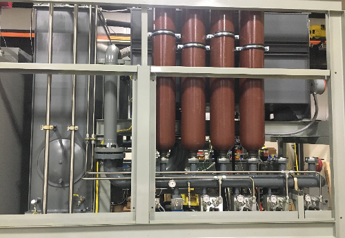
Figure 2. The “Muscle” of the Test Stand Assembly included multiple accumulators, storage reservoirs, and control valves.
Building the Brains of the Test Rig
The test application is powered by National Instruments (NI) LabVIEW and NI cRIO Real-Time (RT) embedded controller and Data Acquisition (DAQ) System.
A PC desktop computer provides a user interface to the operator.
The machine also utilized a PLC to maintain system safety (e.g. interlocks, alarms, and status). Handshaking between the test application and the PLC ensures that loss of communications to the PC or RT test application will safely shut the system down.
Fourteen (14) custom-configured operator screens provide a wide range of control and monitoring:
- Main Control/Status screen
- Manual screen
- Simulation Targets screen
- Graph Display screen
- Digital Display screen
- System Configuration screen
- Input and Output Calibration screens
- Failure Log
- Fault Database Log
- Test Database
- Application-Specific Control and Monitoring screens
- Current Job Test Values
- Recommended Adjustment Settings
- Calibration screen
Several position displays were also included to provide the operator a “physical sense” of the simulated load location during testing.
Conclusion
Genuen was able to engineer, build, and deliver a system, which many believed to be impossible. This enabled the customer to eliminate the need for either multiple physical test cylinders or the physical interpolation of sizes and varying loads. System test time(s), installation time, and field-adjustment concerns have been greatly reduced. System documentation provides installation instructions as well as a base-line, “as shipped” point of reference to return to should the system become out of adjustment in the future.
Ready to Get Started?
Learn more about our products or request a consultation with an experienced engineer.