Industry: Automotive, Transportation
Application: Custom Test Solutions
 The Challenge
Building an end-of-line production test stand for automotive oil pumps, developed with NI LabVIEW and capable of meeting multiple machine motion requirements and high-volume throughput goals.
 Background
A major supplier of automotive oil pumps needed to create an end-of-line production test stand for a new line of pumps. To support the new system, the customer needed the application written in NI LabVIEW, and for it to interact seamlessly with the existing assembly line process control database. The new test stand needed to be fully automated, able to control multiple machine motions, and meet a cycle time of 45 seconds or less to produce 200,000-300,000 units annually.
 The Solution
The new oil pump is a dual-pump design – consisting of a variable displacement main pump and a fixed displacement scavenge pump – typically found in high-performance cars employing a dry sump oiling system. In these types of systems, a remote oil tank supplies the main variable displacement pump that provides oil under pressure to the engine’s moving parts for lubrication and cooling. A second scavenge pump pulls leftover oil from the oil pan – also known as “sump” – and returns it to the oil tank. These dual-pump systems have two inlet ports and two outlet ports, although the same drive shaft engages both pumps from a test stand driveline via a Torx screwhead.
Break-Ins and Performance Points
Conventional pump testing involves subjecting the oil pump to a break-in or “run-in” period, followed by a series of steady-state pressure and flow performance test points to determine the pump's efficiency under varying conditions. As well, the pump’s outlet flow may even be intentionally shut off completely or “dead-headed” to test the on-board pressure relief valve setting (for fixed-displacement pumps) or compensator setting (for variable displacement pumps).
The break-in run helps remove debris left over from the machining process and can expedite wear-in time for moving parts, which often generates fluid contamination. This contamination eventually tapers off to an acceptable level, and with today’s tighter machining tolerances, break-in periods can be significantly reduced compared to years ago.
Engineers then establish pressure and flow performance points based on observed backpressure, taking into consideration pump type (variable or fixed displacement), prime mover type (variable or fixed speed), and downstream valving type (servo or other pressure-regulating valves). For example, for a variable displacement pump, the prime mover speed can remain constant while adjusting pump displacement to achieve different flow rates. Conversely, for a fixed displacement pump, flow rate can be adjusted by varying pump speed.
Since in this application, the pump combines a variable displacement main pump with a fixed displacement scavenge pump, the prime mover motor is controlled by a variable frequency drive (VFD).
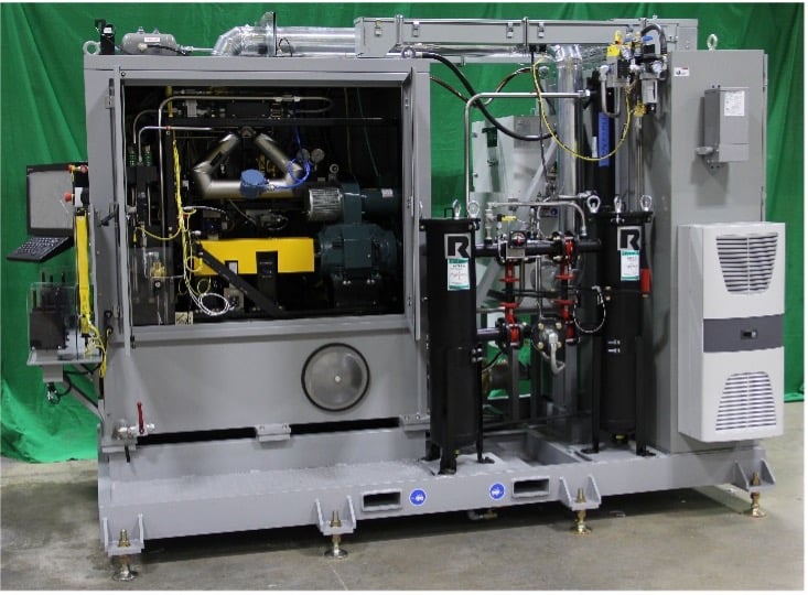
The back pressure observed by the pump under test was created using two fixed-sized orifice plates in series instead of pressure-regulating valves. These plates were sized to create a known back pressure and differential pressure across a Coriolis flow meter positioned between the plates at a known flow rate. The created differential pressure is used as a load sense to adjust the displacement. By using these fixed-size orifice plates, cycle time is reduced since the test stand no longer needs to adjust valves using a PID control algorithm to achieve a desired backpressure.
Pump Test Process
To further reduce valuable cycle time, the test stand is divided into three stations: a load (or “on-deck” station) with a fixed-mount 2D barcode scanner, a test station, and an unload station.
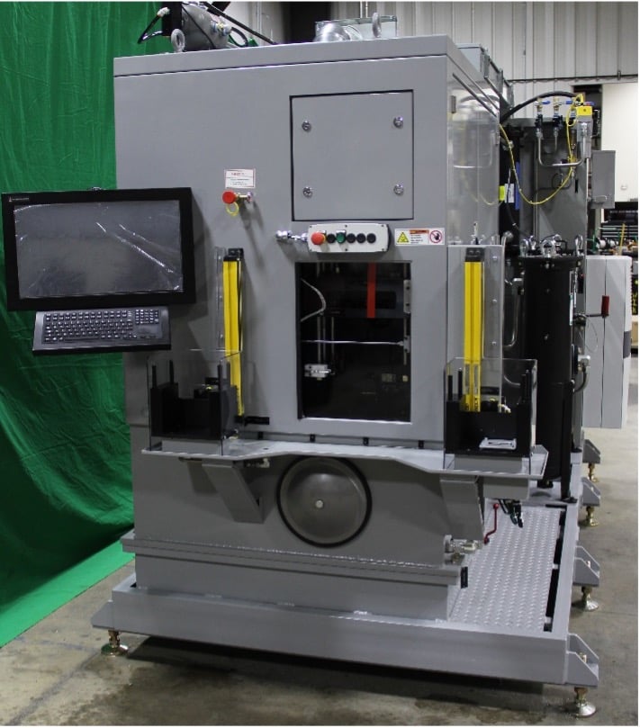
To begin the testing process, the test stand operator first places a pump into a nest at the load station, and a part presence sensor signals the software that a pump is present. The software triggers the scanner to read the barcode, then conducts a series of checks on the pump by interacting with the assembly line process control database, including verifying that the pump has not previously been tested and that it has passed all upstream processes.
If all checks good, the software gives the operator the green light to test the pump. The operator takes the pump and places it into the nest at the test station and plugs in the electrical connection that controls pump displacement. A light curtain surrounds the entry door to the test station and serves as an electrical safety interlock as well as a trigger to the test stand software that the operator has cleared the area. After the operator clears the light curtain, the test stand software checks for pump presence in the test station and to see that an electrical connection to the pump has been established, both actions accomplished with prox sensors. If both checks are true, the software closes a pneumatically actuated Lexan door to shield the operator from hydraulic spray, then raises the pump in the nest to clamp it in place.
Once the pump at the test station is clamped, the software simultaneously advances two hydraulically actuated slides: one from the rear of the pump consisting of the driveline (i.e., prime mover motor and torque cell) that engages the Torx screw on the pump, and the other from the side of the pump that couples to the pump inlet ports. At this time, the test stand software begins testing the pump per the programmable test sequence the customer can define using a test sequence profile editor.
After testing is complete, the two hydraulic slides retract, and the test stand initiates an air-purge cycle to flush oil out of the pump with compressed air. The system then lowers the pump and opens the Lexan door for the operator to retrieve the pump and place it in the unload station for additional draining. This three-station approach keeps the process moving smoothly and helps increase throughput, since, once the operator’s arms clear the light, the operator is free to take the next pump and place it in the load station and move the previously tested pump from the unload station to a cart for clean-up and pack out.
Software Design Considerations
In this type of large LabVIEW application that combines machine control with test and measurement, a sound architecture is critical for scalability and maintainability. This can be achieved by distributing the application into multiple asynchronous parallel processes – or loops – where each loop performs a dedicated and more simplified task.
For example, multiple physical stations necessitate using multiple parallel services: one to monitor the placement of a pump into the load station nest, scan the barcode, and perform all the database lookup checks; and another service to monitor the pump placement in the test station and perform the actual test.
Also, in a traditional machine controls application, a PLC is often the instrument of choice for handling motion control and safety logic. However, in the case of this test stand, there was no PLC. Instead, a programmable safety controller handled the important safety-related I/O, such as E-Stop pushbuttons, light curtain state, STO to the main VFD, etc. But even having a dedicated safety controller does not protect against potential erroneous digital output being enabled without all permissives being met, potentially causing a crash.
To address this, engineers implemented a process control loop in the test stand software to review the requested state for every discrete output, only allowing approval if all permissives are met. If any are not met, the requested state reverts to the previous state. Having a single location for this logic makes the program easier to maintain compared to duplicating it throughout the program.
Engineers also solved issues caused by the separation of the test sequence from the machine control sequence, and the subsequent need for separate editors for each. Oftentimes in a production EOL tester, the machine control sequence that places the test stand into proper configuration on the UUT is hardcoded. This can involve a tedious amount of testing and retesting to get the sequence just right, with every small change requiring code edits by a skilled LabVIEW programmer, followed by recompiling into a stand-alone executable.
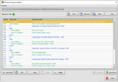
Since in this case there was a fair amount of machine configuration required, engineers ported the machine configuration sequence out to the user interface via a Machine Sequence editor. By doing this, they saved valuable time during debug and commissioning, while also removing the necessity of a LabVIEW programmer for sequence coding. Customers can now also use the editor to make additional modifications after deployment.
The Machine Sequencer includes an intuitive interface with commenting options for each step, as well as access to previously configured sequences for modular reuse in nesting and looping.
The Machine Sequencer also gives users the ability to:
- Loop or repeat a set of steps based on test stand conditions not met (“do while”)
- Dwell for a specified duration
- Branch between different sets of steps based on test stand conditions (“if else”)
- Set digital output states and other test stand conditions such as drive speed
- Set completion requirements before continuing to the next step
- Call a test sequence created by the Test Sequence Editor
Using these capabilities, engineers defined the following machine sequences:
- Abort Test Sequence: Stops the prime mover drive while maintaining all other output states and homes the machine
- Emergency Shutdown Sequence: Shuts down the sequence in the event of a system alarm condition on an analog input channel, an E-stop, or other fault condition resulting from a digital input or a logical state
- Machine Homing Sequence: Retraces all hydraulically and pneumatically actuated slides to their home positions
- Pre-production Test Sequence: Prepares the test stand by raising and clamping the pump in the nest, closing the operator door, and advancing both the driveline slide and inlet slide
- Post-production Test Sequence: Performs the air purge at the end of a pump test and returns the test stand back to home position, allowing the operator to remove the tested pump
Additional Helpful Tools
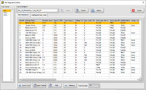
Another key feature is the Test Sequencer, used to set pump conditions, acquire and analyze data, and evaluate pass or fail after the pump is raised and clamped in the nest with both driveline and pump inlet slides advanced. Unlike the Machine Sequencer, it does not allow for adjusting or setting all test stand I/O, but only those that affect the conditions placed upon the pump, such as speed setpoint and pump displacement. Each step of the Test Sequencer allows for setting the pump speed and displacement while applying different types of analysis and pass/fail limits for that step.
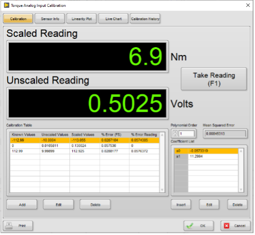
An embedded calibration utility was also installed that allows for complete end-to-end calibration of all analog signals, both input and output. It includes the following features:
- Intuitive user interface for scaled and raw values with large font, offering easy reading from a distance
- Support for dead-weight calibration through raw readings for known applied stimuli
- Data entry for known calibration points (via sensor manufacturer data sheets), span and zero values, and sensor-specific information
- Support for polynomial fits greater than linear
- Calibration restoration to a historical calibration point
- Channel calibration reports
- Calibration tools, like calculation of percent error of full scale, percent error of reading for every point, and mean squared error for the overall calibration
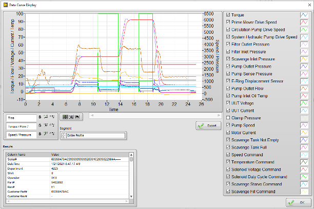
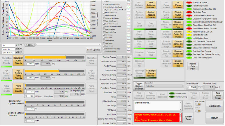
Finally, a Manual Control screen was created to help troubleshoot issues with the test stand or pump. The screen is intuitively designed, grouping I/O by field device and not just I/O type. It includes a waveform graph with a 60-second history, as well as displays for each analog channel and a section dedicated to controlling each of the 3 VFDs used by the system. It also features a section for viewing and controlling the states of various cylinders and valves for machine hydraulic control and pump flow circuits, as well as displays for other digital inputs not assigned to a field device.
Conclusion
The customer was profoundly pleased with this solution for testing its new oil pumps. The tool has proven flexible enough for engineering but also extremely functional for operators, thanks to its user-friendly interface. Since the code was written in an intuitive and easy-to-edit way, with source code included, the customer has been able to make modifications as desired. And as an answer to demanding cycle times, the Machine Sequence and Test Sequence editors have shifted the onus away from the machine builder and software developer, placing more power into the hands of the customer, who now has full control to adjust timing of sequences as necessary.
Ready to Get Started?
Learn more about our products or request a consultation with an experienced engineer.