
The average rate of project failure is 70%, with technical projects having a still greater failure rate. As technology continues to advance at an exponential rate, companies must find a way to reduce the rate of failure in order to remain competitive.
Model-based systems engineering (MBSE) employs modeling to support system requirements, design, analysis, verification, and validation activities. Implementing modeling early in the product development cycle can significantly minimize some of the most common causes of project failure and increase your probability of success. In this blog post, we’ll be exploring two MBSE methodologies: Unified Modeling Language and Model Engineering.

Unified Modeling Language
Unified Modeling Language (UML) is a general-purpose modeling language that utilizes graphic elements as representation for a standard system visualization. It is not only for the determination of a system’s boundaries, the interfaces and components that will be part of the system, but also how they will interact with each other and interface with external components and actors. UML helps the project team visualize the system structure, or what must be present in the system, and the system behavior, or the dynamic behavior the system must incorporate from many vantage points.
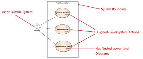
Figure 1 High-level Functionality Use Case Diagram

Figure 2 Lower-level Functionality Use Case Diagram
Model Engineering
The goal of Model Engineering (ME) is to understand the system being created as completely as possible as early as possible in the development cycle. Typical complex control problems benefit from heavy software modeling performed in its early design phases; this is known within project management as Model-Based Design Workflow (MBDW). Typical MDBW includes the following ME activities; Model-in-the-Loop (MIL), Processor-in-the-Loop (PIL), Software-in-the-Loop (SIL) and Hardware-in-the-Loop (HIL) simulation. An MBDW begins with MIL as the basis for simulation and consecutively builds to PIL, SIL, and HIL, changing just one variable in each simulation.
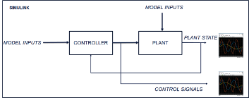
Figure 3 MIL Representation
MIL involves a set of mathematical equations, the models, that best represent the physics of the plant, or the simulated environment, and the controller algorithms. It simulates the system controller within a simulated environment. Once the MIL is thoroughly simulated through a set of inputs to both the controller and the environment, these same inputs are passed down to a PIL model. During the PIL phase, the MIL controller box is replaced with firmware code that is expected to run on the production controller. In the SIL phase of the MBDW, the firmware portion of the model is replaced by its production controller software. Finally, during HIL simulation, the controller hardware running the control algorithm firmware is applied.
To learn more about MBSE, UML, and ME, download our white paper, “Reducing Technical Project Failure with Model-Based Systems Engineering” here.