The Hough Circle Transform has been known for some time.[1] The Hough Circle Transform takes in data and a known radius, and outputs the center of the circle with that radius, that best fits the data. It does this by setting up an accumulator grid, all initialized to zero, in which each data point votes on where it thinks the circle center is. A more formal description follows.
Given: data, and known radius r of the circle to detect.
- Initialize accumulator grid to zeros, of equal size to possible data locations.
- For each data point, find all grid points in an annulus of inner radius r – a and outer radius r + a. Increment the counters corresponding to these grid points.
- The maximum value of the accumulator grid corresponds to the circle center.
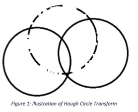
Why does this algorithm work? If you examine Figure 1, the method begins to make sense.

Let us suppose you have incomplete data, represented by the circle with points of its circumference missing. You want to find the center of that circle. So, for each point that is on the circle, you draw a circle of the same radius as the known radius (represented by the two whole circles). Notice that the two whole circles will intersect at the desired circle center. Because of this fact, that point will get voted up in the accumulator grid significantly more than any other point in the grid.
The advantage of the Hough Circle Transform method over other circle-finding routines is that it is robust to a lack of data. I have found that the Hough Circle Transform can find circle centers even when you have at most 5 or 10 degrees of the arc. It works remarkably well.
Currently, the only LabVIEW implementations of the Hough Circle Transform you can find online use the IMAQ libraries from the NI Vision Development Module, which is a paid add-on. In contrast, I have implemented the Hough Circle Transform entirely in native LabVIEW, which you can access by clicking the button below.
There are a couple of optimizations I have implemented in order to make the algorithm run faster. First of all, I have assumed that the entire circle, whether there is data there or not, lies inside the grid. Therefore, we can assume the circle center resides in a centered, inner square of the accumulator grid, where the inner square’s side dimension is the grid size minus one diameter. This allows us to examine a smaller grid. Secondly, I have reversed the order of examination, so that the grid for loops are on the outside. The reasoning here is that we can more easily parallelize the code on the grid locations than on the data values. Why is that? Because each accumulator’s correct final value depends on all the data values, whereas the data values do not depend on the grid locations. If we parallelize on the data values, we end up with a collection of identical full grids that must be added together to get the correct totals. If we parallelize on the grid locations (I did it solely on the rows), each row can simply find the number of data points in range, and increment accordingly, independent of the other rows. You will note that this is a slight modification of the actual Hough Circle transform, but it is equivalent. This is an ideal setup for parallelization, so I have utilized the built-in LabVIEW parallelized for loop on the rows. The result is the below VI, which you can download and examine for yourself. It is written in LabVIEW 2014 SP1.
-----------
Adrian C. Keister, Ph.D. has a background in mathematical physics and develops automation software for electromechanical test systems in the Wineman Technology southeast office located in Raleigh, NC. He also has interests in data science, quantum computing research, writing classical music, and advancing mathematical problem solving via Math Help Boards.
[1] P. V. C. Hough, “Method and means for recognizing complex patterns”, U.S. Patent 3069654 (1962).


